
Self-Managed Kubernetes
All code for this article available here.
Have you ever wanted to run your own IaaS? Maybe you want to host your own projects with Kubernetes, but not pay for a managed service. Or maybe self-managed Kubernetes is your project! For me, it was both, so I set out to learn how to run my own cluster on virtual private servers.
Initially, I thought that installing Kubernetes was going to be the hard part, but it turns out that it's actually pretty straight forward thanks to projects like k0s. Instead, I ended up learning about Cloud-Init, QEMU, Linux virtual networking interfaces, and HAProxy.
Before getting into setting up our cluster, a warning: do not do this for a revenue-generating system! Setting up Kubernetes is one thing, but maintaining that cluster over time and keeping it up-to-date is much harder. My advice to anyone considering Kubernetes for a production system: either be prepared to become a Kubernetes expert, hire an expert, or pay for a managed service. Use Docker Compose for as long as your workload can fit on a single server (most can!).
Table of Contents:
- Overview
- Local Test Environment
- Debian on QEMU with Cloud-init
- Virtual Network
- Bootstrapping the Nodes
- Installing Kubernetes
- Ingress and Load Balancing
- What's Next?
Overview
We'll be walking through how to bootstrap a local cluster of VMs using QEMU, setup a virtual network using the ip command, install Kubernetes using k0s, set up an ingress controller, and use HAProxy as a load balancer.
This tutorial assumes that you're using Linux.
Alright, lets get into it by first setting up our VMs!
Local Test Environment
We'll be creating the VMs using QEMU, all running locally. Initially I considered using VPSs, but local makes more sense when you want to experiment and iterate quickly. The setup could then also serve as a starting point for a Kubernetes CI/CD system or a local development environment, depending on your goals.
Here is a high-level, architectural diagram of what we'll be building:
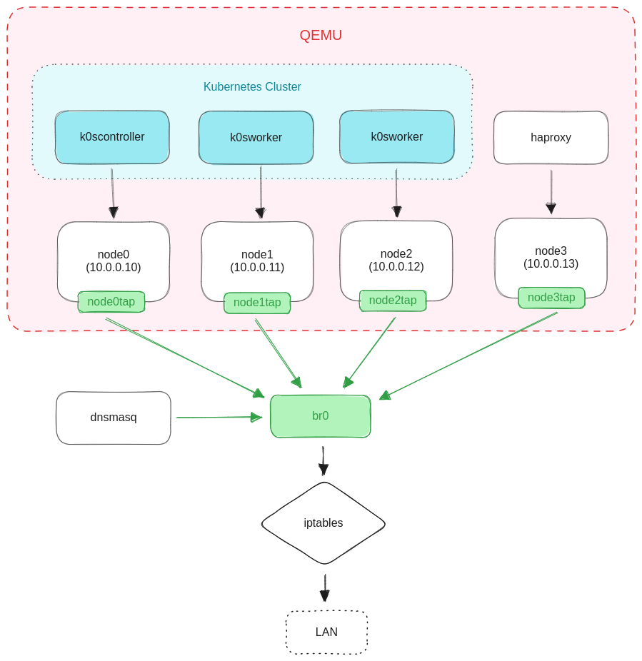
There will be four QEMU VMs in their own private /24 network. Three will be running Kubernetes and the other one will be an HAProxy load balancer. Every node will have a virtual TAP device that is plugged in to the virtual bridge br0. A dnsmasq daemon running on the host will assign IP addresses to our nodes based on their MAC address.
I'm using QEMU, but you could use any Linux virtualization software. VirtualBox or VMWare would work. There's also libvirt which abstracts over different virtualization backends (including QEMU) if that's your thing.
The private network is acting like an emulated VPC. There are iptables rules that allow the nodes to reach the external network.
Each node is configured with a predefined MAC address. dnsmasq will then use the MAC address of a client to assign the IP address configured for that MAC.
You could instead use Cloud-Init to statically assign IP addresses, but you'll then need to create a seed ISO for each node.
The HAProxy node is responsible for reverse proxying external traffic to the Kubernetes nodes.
Debian on QEMU with Cloud-init
We'll be using Debian 12 for the VMs, and specifically the generic cloud image. This image is optimized for VMs by excluding drivers for physical hardware. While not strictly necessary, it gives us a solid foundation if later we decide to manage our own VMs on bare metal servers.
Let's download the latest version of the Debian 12 generic cloud image:
wget -O debian12.qcow2 https://cloud.debian.org/images/cloud/bookworm/latest/debian-12-genericcloud-amd64.qcow2
The downside of this image (or upside if you value minimalism) is that it's not configured with a default user account or root password. In order to login we need to use a tool cloud Cloud-Init to create a "seed ISO" which configures the system as it boots. This is essentially what your cloud provider does every time you spin up a new VPS.
So the basic pattern is: every time we want to create a new VM we clone the base disk image and then boot the VM using that fresh disk image and a seed ISO. If each VM needs to be configured differently, then we'd generate a new seed ISO on the fly with that configuration.
In our case, all of our VMs will be configured with our SSH public key so we can login remotely from a terminal.
We'll use the cloud-localds tool to create the seed ISO file. If you're on Ubuntu, you will need to install the cloud-image-utils package:
sudo apt install cloud-image-utils
Then we create a cloud-config file cloud_init.yaml:
#cloud-config
users:
  - name: root
    ssh-authorized-keys:
      - <YOUR_SSH_PUBLIC_KEY>
Substitute in your public key and then run cloud-localds:
cloud-localds -v seed.iso cloud_init.yaml
Which should result in an ISO file seed.iso.
$ file seed.iso
seed.iso: ISO 9660 CD-ROM filesystem data 'cidata'
Next let's clone the base disk image that we downloaded:
cp ./debian12.qcow2 ./test.qcow2
Now we can boot a VM using the disk image and seed ISO:
sudo qemu-system-x86_64 \
    -m 2G \
    -smp 2 \
    -device virtio-net-pci,netdev=net0 \
    -netdev user,id=net0,hostfwd=tcp::2222-:22 \
    -drive file=./test.qcow2,if=virtio,cache=writeback,discard=ignore,format=qcow2 \
    -drive file=./seed.iso,media=cdrom \
    -boot d \
    -serial stdio \
    -machine type=pc,accel=kvm
QEMU has a lot of different flags, so let's break this command down:
qemu-system-x86_64: QEMU uses separate executables for different guest system architectures. Here's we're telling QEMU to create an x86_64 guest.
-m 2G: The amount of memory.
-smp 2: The number of CPU (vCPU) cores.
-device virtio-net-pci,netdev=net0: Creates a virtual network interface card and use the net0 network backend. QEMU separates networking devices from networking backends. The device is the part that the guest system sees and the backend is what plugs in to the host environment.
-netdev user,id=net0,hostfwd=tcp::2222-:22: Creates a network backend with the name net0. We're using the "user networking" (or SLIRP) backend type and forwarding traffic from port 2222 on the host to port 22 on the guest.
-drive file=./test.qcow2,...: Creates a virtual disk drive using the cloned Debian disk image.
-drive file=./seed.iso,...: Creates a virtual CD-ROM drive with the seed ISO inserted.
-boot d: Instructs the VM to boot from the CD-ROM drive. In our case this boots the seed ISO which will then configure the system.
-serial stdio: Redirects the virtual console to stdout on our terminal for easier debugging. We do this mainly so that we can scroll back through the output.
-machine type=pc,accel=kvm: Instructs QEMU to use KVM acceleration. This leverages native virtualization support on the host using the KVM kernel module.
Alright, so after running that command the QEMU GUI will open and the VM will start to boot. We should see the virtual console output in the GUI and our terminal. Notice the cloud-init and ci-info log messages, one of which will reference your configured public key.
After the VM finishes booting up you should be able to login over SSH on port 2222:
ssh root@localhost -p 2222
That was just a test VM. Next we're going to setup the virtual network and then create a VM for each of our four nodes.
Virtual Network
As mentioned before, the test VM we just created is using the "user networking" backend type. This backend is great for testing, but has poor performance and isolates each VM to its own network. We want to create a cluster of VMs running on a single virtual network, so we therefore need to use a different networking backend.
Let's take a looking at that diagram again:
There are four core networking components:
- The bridge device
br0acts as a virtual switch that our VMs are all plugged into, forming a virtual LAN. - Each VM has its own TAP device connected to it. The TAP device is then "plugged into" the bridge and forwards packets across the VM's virtual network interface card.
- A
dnsmasqdaemon running as a DHCP server assigns IP addresses to the nodes. iptablesrules that makebr0act like a NAT router, allowing nodes to access the internet.
Let's create the virtual bridge device using the ip command, assign it the IP address 10.0.0.0/24, and bring it online:
# Create the bridge
sudo ip link add br0 type bridge

# Assign an address to the interface. If we don't do this then dnsmasq will later complain that the interface it is bound to "has no address"
sudo ip addr add 10.0.0.0/24 dev br0

# Bring the bridge up
sudo ip link set up dev br0
Check that the device was created:
ip -d link show br0
You should see something like this:
159: br0: <BROADCAST,MULTICAST,UP,LOWER_UP> mtu 1500 qdisc noqueue state UP mode DEFAULT group default qlen 1000
    link/ether 6a:09:53:74:75:05 brd ff:ff:ff:ff:ff:ff promiscuity 0  allmulti 0 minmtu 68 maxmtu 65535
    bridge [...]
Next we need to create a TAP device for each of the four nodes that we'll be creating:
for NODE_NAME in node0 node1 node2 node3; do
    echo "${NODE_NAME}tap"

    # Create the TAP device
    sudo ip tuntap add "${NODE_NAME}tap" mode tap

    # Bring it up
    sudo ip link set "${NODE_NAME}tap" up

    # Plug it into the bridge
    sudo ip link set "${NODE_NAME}tap" master br0
done
Take note of the interface names we echo out; we'll need them later when we configure the VM networking backends.
Again, we can check that each TAP device was actually created:
ip -d link show node0tap
Which should look similar to this:
160: node0tap: <BROADCAST,MULTICAST,UP,LOWER_UP> mtu 1500 qdisc pfifo_fast master br0 state UP mode DEFAULT group default qlen 1000
    link/ether e6:7d:17:30:0d:e5 brd ff:ff:ff:ff:ff:ff promiscuity 1  allmulti 1 minmtu 68 maxmtu 65521
    tun type tap pi off vnet_hdr on persist on
    bridge_slave [...]
Next we're going to configure dnsmasq to run as a daemon on the host. It will act as a DHCP server and network gateway for our nodes.
Here's our dnsmasq.conf file:
# Bind to the bridge device
interface=br0
bind-interfaces

# Ignore host /etc/resolv.conf and /etc/hosts
no-resolv
no-hosts

# Forward DNS requests to a public DNS resolver
domain-needed
bogus-priv
server=8.8.8.8
server=8.8.4.4

# Serve leases to hosts in the network
dhcp-range=10.0.0.0,10.0.0.255

# Lease these IPs to nodes with the given MAC address
dhcp-host=86:e2:e3:21:13:b4,10.0.0.10,node0
dhcp-host=7c:92:6e:84:1f:50,10.0.0.11,node1
dhcp-host=b0:aa:4c:4c:7b:1a,10.0.0.12,node2
dhcp-host=a6:fc:4a:66:8f:c9,10.0.0.13,node3
The tree most important parts are:
- Binding
dnsmasqto our bridge device. - Forwarding DNS requests to
8.8.8.8and8.8.4.4. - Assigning IPs to our VMs based on their MAC address.
Finally, to start the dnsmasq daemon run this:
sudo dnsmasq \
    --no-daemon --conf-file=./dnsmasq.conf \
    > dnsmasq.log 2>&1 &

echo $! > dnsmasq.pid
This will spawn dnsmasq into the background, redirect all of its output to the file dnsmasq.log, and write its PID to dnsmasq.pid. We can later use the PID to kill the the daemon when we're finished.
The last thing we need to do is append three iptables rules so that the nodes will be able to reach the internet:
sudo iptables -t nat -A POSTROUTING ! -o br0 --source 10.0.0.0/24 -j MASQUERADE
sudo iptables -A FORWARD -i br0 -j ACCEPT
sudo iptables -A FORWARD -o br0 -j ACCEPT
Without these rules, it's possible to reach the nodes from the host (SSH into them etc), but the nodes won't be able to reach the LAN or internet.
And to remove the rules after we're finished use the -D flag:
sudo iptables -t nat -D POSTROUTING ! -o br0 --source 10.0.0.0/24 -j MASQUERADE
sudo iptables -D FORWARD -i br0 -j ACCEPT
sudo iptables -D FORWARD -o br0 -j ACCEPT
That's it! We're now ready to create our VMs and bootstrap the Kubernetes cluster.
Bootstrapping the Nodes
Now that we have a virtual network, it's time to create the actual nodes. First we make a clone of our base disk image, one for each node, and resize it to a comfortable 10 GB:
for NODE_NAME in node0 node1 node2 node3; do
    # Clone the base image
    cp ./debian12.qcow2 "./${NODE_NAME}.qcow2"

    # Resize the new image
    qemu-img resize "./${NODE_NAME}.qcow2" 10G
done
You'll notice that the disk images don't actually take up 10 GB of physical space. That's because the
qcow2file format is sparse and only grows as needed up to the max size.
Next we use the familiar qemu-system-x86_64 command to create our first node node0:
NODE_NAME="node0"
NODE_MAC="86:e2:e3:21:13:b4"
NODE_DISK="./${NODE_NAME}.qcow2"

sudo qemu-system-x86_64 \
    -name "$NODE_NAME" \
    -m 2G \
    -smp 2 \
    -device "virtio-net-pci,netdev=${NODE_NAME}tap,mac=${NODE_MAC}" \
    -netdev "tap,id=${NODE_NAME}tap,ifname=${NODE_NAME}tap,script=no" \
    -drive "file=./${NODE_DISK},if=virtio,cache=writeback,discard=ignore,format=qcow2" \
    -drive "file=./seed.iso,media=cdrom" \
    -boot d \
    -machine type=pc,accel=kvm &
I've factored out some of the values into shell variables so we can more easily read what's going on here. But it should look similar to the test VM we made earlier.
With -device we explicitly sets the MAC address of the network interface card. The dnsmasq daemon will then lease the IP address 10.0.0.10 to this node.
With -netdev we use the tap network backend type and reference the name of the TAP device, node0tap, that we created earlier. We also set script=no so that QEMU doesn't try to automatically setup any additional host networking devices.
The
scriptoption defaults toscript=yeswhich will try and automatically setup a bridge device for us when using thetapnetworking backend. Since we already created a bridge device we need to disable this.
We then create two virtual drives with -drive just like before, but this time using the freshly cloned node disk image.
Notice that we spawn the process into the background using
&so we can create all of our VMs in the same terminal window. If something goes wrong, you can add the-serial stdiooption and run each VMs in their own terminal to inspect the virtual console output.
The VM will then start to boot up. If we check dnsmasq.log we should see the daemon lease an IP address to the node:
$ watch -n0.1 cat ./dnsmasq.log
...
dnsmasq-dhcp: DHCPDISCOVER(br0) 86:e2:e3:21:13:b4
dnsmasq-dhcp: DHCPOFFER(br0) 10.0.0.10 86:e2:e3:21:13:b4
dnsmasq-dhcp: DHCPREQUEST(br0) 10.0.0.10 86:e2:e3:21:13:b4
dnsmasq-dhcp: abandoning lease to 86:e2:e3:21:13:b4 of 10.0.0.10
dnsmasq-dhcp: DHCPACK(br0) 10.0.0.10 86:e2:e3:21:13:b4 node0
Once the node has an IP address, we can login over SSH:
ssh [email protected]
Create three more nodes, making sure to use the correct TAP interface name and MAC address. Once all four are up and running we can finally install Kubernetes!
Installing Kubernetes
Just like Linux, there are many different distributions of Kubernetes, each with their own installation method. For this tutorial we'll be using k0s. It installs itself as a single, statically linked binary running as a systemd service.
There are other single-binary Kubernetes distributions we could choose. k3s is a popular choice that focuses on ease of use and low-resource environments, while k0s focuses on minimalism and a more pure, upstream Kubernetes experience.
k3s includes an ingress controller and load balancer right out of the box, while k0s doesn't bundle any additional tools. We'll be sticking to k0s since it's a solid foundation to build on, but if you're in a resource constrained environment (for example, Raspberry PIs) then k3s is worth taking a look at.
The k0s project includes the k0sctl CLI tool,which is the recommended method for performing a remote installation.
Install the latest version of k0sctl and then create the follow cluster config:
apiVersion: k0sctl.k0sproject.io/v1beta1
kind: Cluster
metadata:
  name: local-cluster
spec:
  hosts:
  - role: controller
    installFlags:
    - --debug
    ssh:
      address: 10.0.0.10
      user: root
      port: 22
      keyPath: ~/.ssh/id_ed25519
  - role: worker
    installFlags:
    - --debug
    ssh:
      address: 10.0.0.11
      user: root
      port: 22
      keyPath: ~/.ssh/id_ed25519
  - role: worker
    installFlags:
    - --debug
    ssh:
      address: 10.0.0.12
      user: root
      port: 22
      keyPath: ~/.ssh/id_ed25519
  k0s:
    version: 1.27.5+k0s.0
    dynamicConfig: true
Here we're referencing each of our Kubernetes nodes by their IP address and telling k0sctl to login in remotely using the given SSH identity file.
Each node has a role which can be either "controller" or "worker".
Controller nodes form the control plane and - unsurprisingly - run Kubernetes control plane components. Worker nodes run your application workload and are what you see in the output of kubectl get nodes.
For this tutorial we're running a single controller node. In production you would run
2*k + 1controller nodes, wherekis the number of node failures the cluster should be able to tolerate. Ideally, each controller node would run in a different failure zone.
All we have to do now is tell k0sctl to apply our cluster configuration to the nodes:
The command may take a long time to download the k0s binary, especially if you get throttled by GitHub like me. In that case, you may want to download the latest binary yourself from their GitHub releases page and manually install it to
/usr/local/bin/k0sas a part of the base disk image.
k0sctl --debug apply \
    --config ./k0sctl.yaml \
    --kubeconfig-out kubeconfig
After this command runs you'll have a kubeconfig file in the current working directory which you can use to connect to the cluster using kubectl.
If anything goes wrong
k0sctlwill tell you the path of an error log file on your system. For me it was~/.cache/k0sctl/k0sctl.log.
Confirm that the cluster is running:
KUBECONFIG=./kubeconfig kubectl get pods -A
You should see something like the following:
NAMESPACE       NAME                                        READY   STATUS             RESTARTS        AGE
kube-system     coredns-878bb57ff-l7c8p                     1/1     Running            1 (3m52s ago)   59m
kube-system     coredns-878bb57ff-tl4nx                     1/1     Running            1 (3m53s ago)   59m
kube-system     konnectivity-agent-6bdm5                    1/1     Running            1 (3m53s ago)   59m
kube-system     konnectivity-agent-fcssv                    1/1     Running            1 (3m52s ago)   59m
kube-system     kube-proxy-5lpg2                            1/1     Running            1 (3m52s ago)   59m
kube-system     kube-proxy-c8tbq                            1/1     Running            1 (3m53s ago)   59m
kube-system     kube-router-n4q7s                           1/1     Running            1 (3m53s ago)   59m
kube-system     kube-router-xtzkk                           1/1     Running            1 (3m52s ago)   59m
kube-system     metrics-server-7cdb99bf49-zwgvm             1/1     Running            2 (3m13s ago)   59m
Now that we have a working Kubernetes cluster, the next step is to setup an ingress controller and external load balancer so that traffic can get to our pods.
Ingress and Load Balancing
In Kubernetes, the ingress controller manages the routing of HTTP traffic to the services of your application. However, it does not define how external traffic actually reaches the ingress controller in the first place.
When you use a managed Kubernetes service like GKE or EKS, you may have noticed that the ingress controller's service is of the type LoadBalancer.
This signals to the cloud environment that it should provision an external load balancer for that cluster. The ingress controller will then receive an EXTERNAL IP which is an externally accessible IP address associated with the load balancer. External traffic received by the load balancer on that address will then be proxied to the cluster's ingress controller.
Since we don't have a cloud environment, we need to setup a load balancer ourselves. That's where the fourth node comes in.
In Kubernetes, services can be of the type
ClusterIP,NodePort,LoadBalancer, orExternalName. Reading the docs you'll see that as far as Kubernetes is concerned, theLoadBalancertype doesn't actually do anything. This is a common point of confusion when trying to learn Kubernetes in a cloud environment (well, at least it was for me!).
First we need to actually install an ingress controller. We'll be using ingress-nginx. Then we'll install HAProxy on node3 and configure it to reverse proxy all HTTP and HTTPS traffic it receives to the ingress controller.
More specifically, the ingress controller will be configured with a NodePort service that HAProxy will be able to reference as a reverse proxy backend.
The network flow will look something like this:
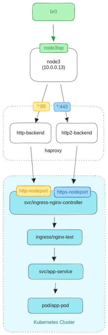
The ingress controller's NodePort service exposes ports on each worker node. HAProxy then reverse proxies the HTTP(S) traffic it receives to those ports.
Alright, so now we need to install ingress-nginx. We apply the "baremetal" manifest as per the documentation for setting up a NodePort service.
kubectl apply -f https://raw.githubusercontent.com/kubernetes/ingress-nginx/controller-v1.8.2/deploy/static/provider/baremetal/deploy.yaml
In a production cluster you should instead use the Helm installation method which will help automate the process of upgrading the ingress controller.
Once the ingress controller finishes installing you should see something like this:
$ kubectl get pods -n ingress-nginx
NAME                                        READY   STATUS      RESTARTS   AGE
ingress-nginx-admission-create-dv4p7        0/1     Completed   0          60s
ingress-nginx-admission-patch-7htxb         0/1     Completed   2          60s
ingress-nginx-controller-79bc9f5df8-vpmrw   0/1     Running     0          60s
Let's take a look at the ingress controller's service:
$ kubectl get -n ingress-nginx svc
NAME                                 TYPE        CLUSTER-IP      EXTERNAL-IP   PORT(S)                      AGE
ingress-nginx-controller             NodePort    10.106.85.180   <none>        80:30299/TCP,443:30448/TCP   85s
ingress-nginx-controller-admission   ClusterIP   10.105.197.7    <none>        443/TCP                      85s
The service ingress-nginx-controller is of type NodePort, as expected, and has allocated the port 30299 for HTTP and 30448 for HTTPS. Take note of these as we'll need them to configure HAProxy.
Your ports may be different than mine! Kubernetes will allocate ports from a pre-configured range based on availability. The ports do not change unless manually deallocated (such as when deleting the service).
Now that the ingress controller is installed and ready to use, we can install HAProxy on the load balancer node:
ssh "root@$10.0.0.13" "apt-get update -y && apt-get install -y haproxy=2.6.\*"
And check that it's running:
$ ssh [email protected] systemctl status haproxy
● haproxy.service - HAProxy Load Balancer
     Loaded: loaded (/lib/systemd/system/haproxy.service; enabled; preset: enabled)
     Active: active (running) since Wed 2023-09-27 18:03:55 UTC; 21s ago
       Docs: man:haproxy(1)
             file:/usr/share/doc/haproxy/configuration.txt.gz
   Main PID: 1186 (haproxy)
      Tasks: 3 (limit: 2353)
     Memory: 41.9M
        CPU: 108ms
     CGroup: /system.slice/haproxy.service
             ├─1186 /usr/sbin/haproxy -Ws -f /etc/haproxy/haproxy.cfg -p /run/haproxy.pid -S /run/haproxy-master.sock
             └─1188 /usr/sbin/haproxy -Ws -f /etc/haproxy/haproxy.cfg -p /run/haproxy.pid -S /run/haproxy-master.sock

Sep 27 18:03:55 node3 systemd[1]: Starting haproxy.service - HAProxy Load Balancer...
Sep 27 18:03:55 node3 haproxy[1186]: [NOTICE]   (1186) : New worker (1188) forked
Sep 27 18:03:55 node3 haproxy[1186]: [NOTICE]   (1186) : Loading success.
Sep 27 18:03:55 node3 systemd[1]: Started haproxy.service - HAProxy Load Balancer.
If we trying going to http://10.0.0.13 in a browser we'll get a connection error since we haven't configured HAProxy with any backends yet.
To do that, we'll use the following config:
global
    log /dev/log local0
    log /dev/log local1 notice
    chroot /var/lib/haproxy
    stats socket /run/haproxy/admin.sock mode 660 level admin
    stats timeout 30s
    user haproxy
    group haproxy
    daemon

defaults
    log	global
    mode http
    option httplog
    option dontlognull
    timeout connect 5000
    timeout client 50000
    timeout server 50000
    timeout http-request 10000
    errorfile 400 /etc/haproxy/errors/400.http
    errorfile 403 /etc/haproxy/errors/403.http
    errorfile 408 /etc/haproxy/errors/408.http
    errorfile 500 /etc/haproxy/errors/500.http
    errorfile 502 /etc/haproxy/errors/502.http
    errorfile 503 /etc/haproxy/errors/503.http
    errorfile 504 /etc/haproxy/errors/504.http

frontend http-frontend
    bind *:80
    default_backend http-backend

backend http-backend
    server node1 10.0.0.11:30299
    server node2 10.0.0.12:30299

frontend https-frontend
    mode tcp
    option tcplog
    bind *:443
    default_backend https-backend

backend https-backend
    mode tcp
    server node1 10.0.0.11:30448
    server node2 10.0.0.12:30448
This configures two frontends and two backends; one for HTTP and the other for HTTPS.
A frontend is a socket that HAProxy binds to and accepts packets on. A backend reverse proxies packets from some frontend to a server. Here we're proxying HTTP(S) traffic to the two worker nodes on the exposed node ports.
Notice that the HTTPS frontend and backend have the option mode tcp. Using an HTTPS frontend with a mode tcp backend is called is called TLS passthrough . It tells HAProxy to just pass the encrypted TCP packets through to the backend servers without trying to decrypt them.
This enables us to keep certificate management confined to Kubernetes. Otherwise, we'd have to install our HTTPS certificates into both the ingress controller the load balancer.
Let's test that the config works:
$ curl -ik https://10.0.0.13
HTTP/2 404
date: Wed, 27 Sep 2023 18:24:38 GMT
content-type: text/html
content-length: 146
strict-transport-security: max-age=15724800; includeSubDomains

<html>
<head><title>404 Not Found</title></head>
<body>
<center><h1>404 Not Found</h1></center>
<hr><center>nginx</center>
</body>
</html>
Now we get a 404 instead of a connection error. Notice that it's an Nginx error, which means we are reaching the ingress controller from the load balancer!
We're finally ready to deploy an application to the cluster. Let's use this whoami container and configure a deployment, service, and ingress route:
apiVersion: apps/v1
kind: Deployment
metadata:
  name: whoami-test
  labels:
    app.kubernetes.io/name: whoami
spec:
  replicas: 3
  selector:
    matchLabels:
      app.kubernetes.io/name: whoami
  template:
    metadata:
      labels:
        app.kubernetes.io/name: whoami
    spec:
      containers:
        - name: whoami
          image: traefik/whoami:v1.10
          ports:
            - containerPort: 80

---
apiVersion: v1
kind: Service
metadata:
  name: nginx-test
spec:
  selector:
    app.kubernetes.io/name: nginx
  ports:
    - protocol: TCP
      port: 80
      targetPort: 80

---
apiVersion: networking.k8s.io/v1
kind: Ingress
metadata:
  name: nginx-test
spec:
  ingressClassName: nginx
  rules:
    - host: example.com
      http:
        paths:
          - path: /
            pathType: Prefix
            backend:
              service:
                name: nginx-test
                port:
                  number: 80
This is just boilerplate Kubernetes. In the ingress spec we reference the ingress controller by setting ingressClassName to nginx, and in the rules we use example.com as our host.
Let's test the endpoint!
$ curl -ik -H 'Host: example.com' http://10.0.0.13
HTTP/1.1 200 OK
date: Wed, 27 Sep 2023 18:45:20 GMT
content-type: text/plain; charset=utf-8
content-length: 429

Hostname: whoami-test-6747545df6-m9mcg
IP: 127.0.0.1
IP: ::1
IP: 10.244.0.20
IP: fe80::90f6:43ff:fe75:d8f6
RemoteAddr: 10.244.1.8:51950
GET / HTTP/1.1
Host: example.com
User-Agent: curl/7.88.1
Accept: */*
X-Forwarded-For: 10.0.0.12
X-Forwarded-Host: example.com
X-Forwarded-Port: 80
X-Forwarded-Proto: http
X-Forwarded-Scheme: http
X-Real-Ip: 10.0.0.12
X-Request-Id: f942bf1e3c5a9e4af9a14b7c4903ad16
X-Scheme: http
If you want to check using a browser: first add the line 10.0.0.13 example.com to your /etc/hosts file. Then you should see the same output.
What's Next?
If you got this far, congratulations you now know the basics of setting up your own Kubernetes cluster!
Applying this to a cluster of VPSs is actually quite easy since you don't need to setup any custom disk images or networking; the cloud provider will do all of that for you!
When installing Kubernetes with k0sctl, be sure to read the docs to properly setup a bastion host so you don't need to give all of your nodes public IP addresses.
Some next steps to enhance your cluster:
- Install Helm
- Install the Local Persistence Volume Static Provisioner to be able to create persistent volumes using your node's attached disks
- Install Harbor to manage container images
- Install cert-manager to automatically manage TLS certificates
- Setup a highly-available Kubernetes API server using keepalived with a virtual IP
All of the code and configuration files for this tutorial are available as a git repository.